Heliostat


This is a seven hour time lapse of our 9 sq-ft heliostat. The collector is a flat plate thermal style collector with a PV cell added for electric generation. During the time lapse the focal point jumps around a little because we were adjusting the aiming to maximize the PV output. We determined that the PV panel was a little too big to be completely within the evenly illuminated area of the focal point, in other words, the outside edges of the panel were illuminates by less than 9x CSP. This uneven illumination of the solar panel causes a significant decrease in electric output. A slightly smaller solar panel would actually increase electrical power output because it would be more evenly illuminated. We were getting between nine and twenty watts of output from a five watt solar panel. Some of our other experiments submerged PV panels suggest that the right sized and shaped panel should be able to achieve at least six times rated output. Notice how the PV panel output decreases with the rise in the water temperature surrounding it.

Location: Colorado (USA)
Elevation: 7200 feet (2196 meters)
Range to target: 30' (9.2 meters)
10 Gallon batch (37.9 liters)
Mirror plane: 9 square feet (.837 square meters)
CSP: 9x

Time
Temp Tank
Temp change
Temp Amb
BTU
Watts Therm
Volts
Amps
Watts PV
Total Watts
11:00
60
-
65
-
-
11.5
1.5
17.3
-
11:30
70
10
67
833.0
488.1
12.0
1.4
16.8
504.9
12:00
81
11
68
916.3
537.0
12.5
1.3
16.3
553.3
12:30
91
10
70
833.0
488.1
13.0
1.4
18.2
506.3
1:00
99
8
72
666.4
388.5
11.5
1.2
13.8
402.3
1:30
108
9
74
749.7
439.3
13.1
1.4
18.3
457.6
2:00
116
8
74
666.4
388.5
11.2
1.3
14.6
403.1
2:30
124
8
75
666.4
388.5
9.0
1.3
11.7
400.2
3:00
131
7
75
583.1
341.7
7.9
1.2
9.5
351.2
3:30
135
4
74
333.2
195.3
6.1
1.2
7.3
202.6
4:00
140
5
74
416.5
244.1
7.1
1.2
8.5
252.6
4:30
142
2
73
166.6
97.7
8.4
1.2
10.0
107.7
5:00
143
1
72
83.3
48.9
8.0
1.2
9.6
58.5
5:30
144
1
71
83.3
48.9
8.0
1.2
9.6
58.5
6:00
144
0
70
-
-
-

Output Graph


9x Heliostat with hybrid PV / hot water collector .
x9 heliostat and PV waterheater The heliostat is 30 feet north of the collector. This picture was taken at the end of the experiment at about 6:30 pm.
PV waterheater front view

Front view of the concentrated PV / hot water solar collector. The aperture is 18" x 18". There is a five watt PV panel submerged in the water inside the collector that provides enough power to continuously run the small 12 vdc re circulation pump.

We were getting almost 20 watts from a five watt panel. We believe the panel would have actually generated more power if it were a little smaller in size and therefore more evenly illuminated. The edges of the focal spot vary in intensity creating the same effect as shading parts of the solar panel. Shading even a small part of a solar panel will greatly reduce or totally kill power output.

pv / water heater recirc pump

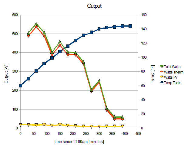
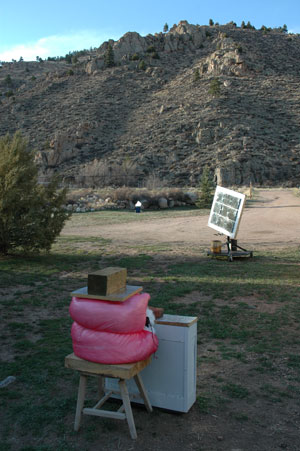
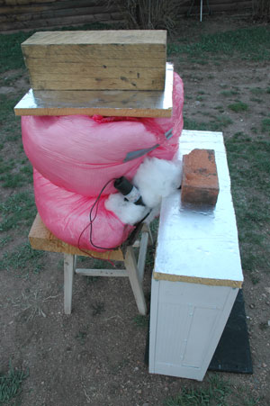
No complex wiring here. The re circulation pump is wired directly to the PV panel. When the sun is out the pump will run, re circulating water from the storage tank, through the solar collector, and back into the storage tank.

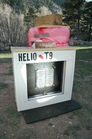
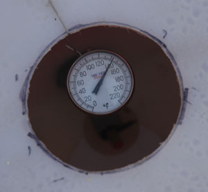
A system like this, left unattended, must include a safety features in case the re circulation system malfunctions. If the re circulation pump stops running the fluid in the collector can quickly rise past the boiling point of water or even antifreeze. This will cause pressure buildup in the system and an explosion if there is not a pressure relief valve.

A temperature sensor in the collector could drive the heliostat of target to keep the collector from overheating in the event of a re circulation malfunction. Another solution could be to cover the aperture of the collector with a heat shield or secondary collector of some kind.

Maximum temperature

Maximum temperature was 144˚F for a ten gallon batch. Not bad for nine little mirrors thirty feet away. Showers anyone?

We left the water tank out all night and checked the temperature the next morning, twelve hours later the temperature of the water in the insulated tank was 120˚F and the temperature of the water in the collector was at ambient temperature 36˚F.

This suggests that the decrease in system efficiency at higher system temperatures is due largely to re-radiation from the collector. It is also possible that the constant re circulation of the water through the poorly insulated pluming between the collector and the storage tank had a lot to do with lower efficiencies at higher temperatures. The only way to really know would be to re run the experiment with controlled variations in the setup and then compare the data collected from each experiment.