
Heliostat Kit
 |
*** Obligatory warning***
This heliostat uses motion actuators that are very strong and capable of causing serious bodily injury if misused.
Although this unit is powered by low voltage it is always necessary to be cautious when using electricity.
The heliostat kit will arrive in four packages, listed below are the contents of each package from smallest to largest...
1)
Bisector & Sun-sensor
Tracking controller
Remote control
2)
Rotary actuator
Aiming bell (2 parts - bell and square tube)
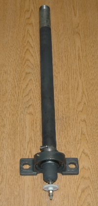
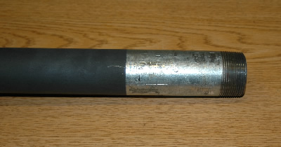
Rotary actuator to aiming bell coupling pipe
3)
Linear actuator
Stand braces
T-Bar arms with mirror plane bearings attached
4)
Mirror Plane Frame
Stand pipe with legs attached
All of the hardware is preloaded into structural parts for quick assembly.
5' Heliostat instructions
*** For this heliostat to work properly the axis of rotation of the rotary actuator must be aligned with the target.
Here are 3 ways of aligning the rotator axis with the target .
1) Sighting holes:
Adjust aiming bell until the center of your target is visible through the sighting holes in the rotator pipe.
You cannot use this method if the mirror plane or linear actuator are mounted to the rotator because they block the sighting holes.
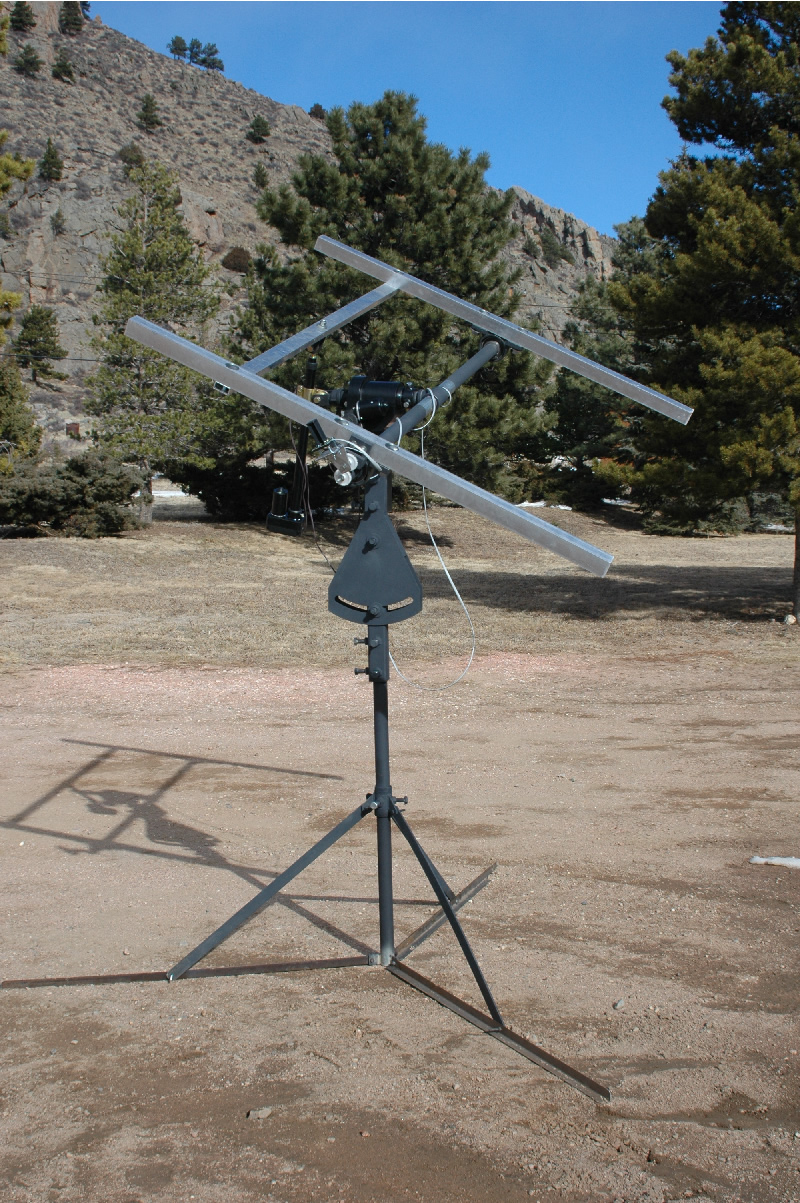
Complete assembly
Now the heliostat is aligned with the target the next step must be done in the sun.
When the sun comes out power up the heliostat and adjust the bisector and sun sensor until the reflected sun is centered on your target.
Aiming is complete
2) Laser sighting:
It works well to use a large sheet of white paper taped over your target so that the laser pointer is more visible, it also provides a surface to mark the path of the laser.
Attach an adjustable laser pointer directly to your mirror plane so that it is aiming toward your target.
Rotate the mirror plane from limit to limit. Use a marker to periodically mark the path of the laser on the paper as you rotate the mirror plane from one limit to the other. The radial point of the laser's path will be the Rotator axis or Target axis that must pass through your target.
Find the exact target axis line by adjusting the laser pointer until it does not move when the mirror plane is rotated from limit to limit, then adjust your aiming bell so that the laser is centered on your target.
Now the heliostat is aligned with the target the next step must be done in the sun.
When the sun comes out power up the heliostat and adjust the bisector and sun sensor until the reflected sun is centered on your target.
Aiming is complete.
Note: Once the bisector is calibrated you can use the aiming bell to align your target axis with any target and the heliostat will automatically adjust until the sun is being reflected along the target axis (unless it reaches a mechanical limit first).
3) Path of reflection:
When the bisector is out of calibration then the reflected sunlight light will travel in an arc around the rotator axis throughout the day. Adjust the bisector and sun sensor until the reflected sun is centered on this observed point then use the "Aiming Bell" to move the sun back to your target.
Aiming is complete.
Assembly instructions.
***It is recommended that the heliostat be setup by at least two people.
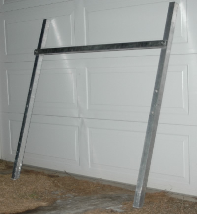 |
Prepare Mirror Plane: This picture is looking at the mirror plane frame from the back (opposite side from mirror) When referring to the right side or left side of the heliostat we will assume that we are looking at it from the back toward the target Remove 5' aluminum bars from package. Attach each end of 1" x 2" cross bar to 2" x 2" aluminum mirror plane mounting bars. Use 2" X 1/2" hardware. Determine how you will attach mirror plane to 2" x 2" aluminum side bars. Drill necessary holes and test mounting. Remove mirror plane after mounting preparation is complete.
|
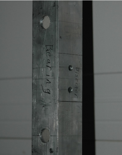 |
When assembling the mirror plane frame, make sure that the spar on the right side has the holes for mounting the bisector. |
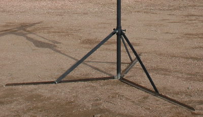 |
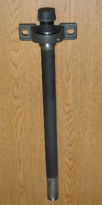
1) Setup stand: The stand legs are already attached to the stand pipe, fold them down and attach the three stand braces between the stand pipe and the legs. Place sandbags or other anchoring weight over stand legs. It is important that the stand not move during aiming and calibration. |
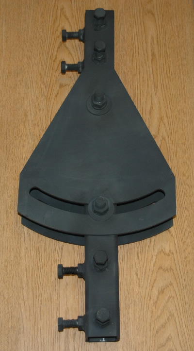 |
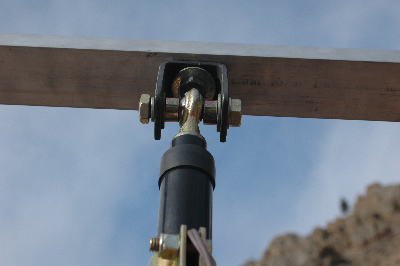
Assemble aiming bell as pictured: Once the heliostat is calibrated you will use the aiming bell to aim the heliostat at whatever target you desire. The aiming bell allows the heliostat target axis to be moved in two directions, azimuth and altitude. Once the aiming bell is assembled then place the square clamping pipe over the stand pipe and tighten the clamping hardware enough so that the aiming bell can still be rotated on the stand pipe without wobbling around too much. There is a label "FRONT (toward target) on the aiming bell. Orient this label toward your calibration target as indicated. A good range for calibrating the heliostat is about 50' - 100' from your target. It is also good if your calibration target is South of the heliostat. (This photo shows the right side of the aiming bell) |
 |
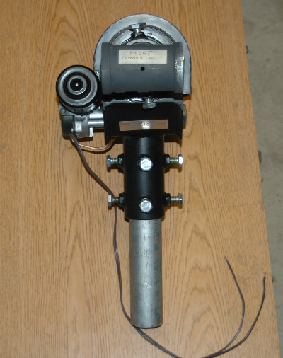
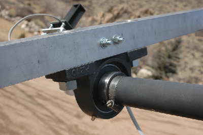
Clamp coupling pipe into rotary actuator: The coupling pipe has been painted black (This photo shows the right side of the rotary actuator) |
 |
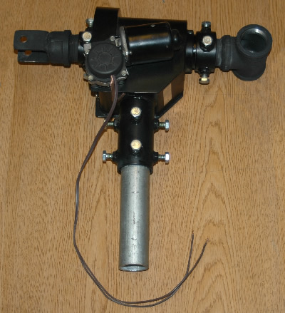
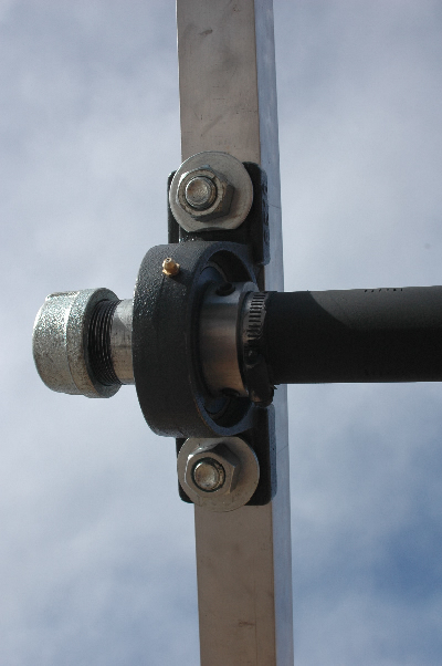
Insert coupling tube and rotary actuator into top of aiming bell and clamp down with clamping hardware. Be sure that both "FRONT" labels are oriented toward the target. (this photo shows the rotary actuator from the front) |
 |
 |
Thread T-Bar arms into "T" coupling: Thread "Left T-bar & Bearing" onto Left side of "T hub" (This part has black end cap. Tighten with pipe wrench until snug.) Thread "Right T-bar & Bearing" onto Left side of "T hub" (This part has threaded rod and stationary bisector gear. Tighten with pipe wrench until snug.) |
 |
Use the T-bar wrench band when tightening the T-bar arms. This will keep the black primer from getting scarred. |
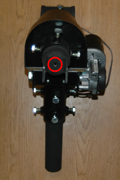 |
Do this step If you will be using "Sighting Hole" method of alignment: Adjust the aiming bell until you can see the center of your calibration target through the sighting holes. You will look through the rear sighting hole (circled in red) Once sighted in on your target clamp aiming bell down and verify alignment. DO NOT move the stand from this point forward or alignment will be compromised and bisector calibration will be difficult. |
 |
Attach the lower linear actuator collar to the rear sighting hole bracket. This is a little tricky, two sets of hands will be a big help help - one person to position the actuator and the other to manage the hardware. Order of hardware 1) Bolt (The picture is missing one washer but it is included in the kit) |
 |
Attach mirror plane frame to T-bar bearings (Photo shows the Left side) |
 |
Attach linear actuator push rod to mirror plane frame crossbar and mount your mirror plane to frame. |
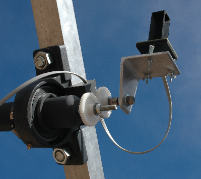 |
Attach bisector and sun sensor to right side of mirror plane mounting bar. Press "mirror plane bisector" gear firmly into "T-bar bisector gear" and tighten bisector mounting hardware. ***When calibrating the bisector you will need to loosen the stationary bisector gear, this is the nylon gear at the end of the t-bar arm. You will need two wrenches to do this job. |
 |
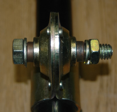
Here are the locking nuts for the bisector mounting hardware. |
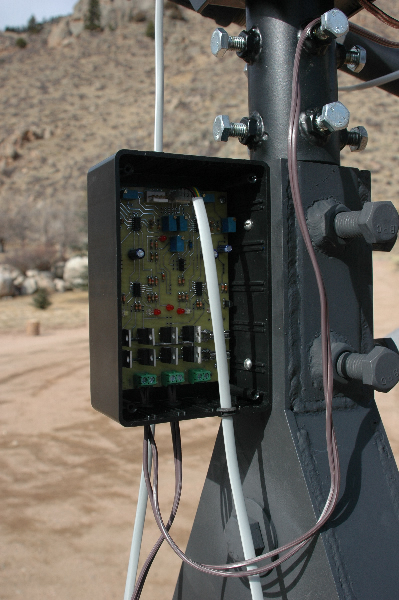 |
Mount controller to Left side of aiming bell and connect wires. The black ended wire from the rotary actuator goes into terminal MW1b the brown end goes to terminal MW1a . The black ended wire from the linear actuator goes into terminal MW2b the brown end goes to terminal MW1a . Leave the sun-sensor plug disconnected for the moment. Now connect power to the controller and wait for about 30 seconds. Plug the remote control into one of the 5 pin plugs on the controller board so we can test the actuators. Stand behind the heliostat looking toward the target. hold the remote so that the cable leads toward the heliostat. The switch that moves from left to right controls the rotary actuator, flipping the switch should rotate the mirror clockwise toward the West. The switch that moves forward and back controls the linear actuator, flipping the switch forward will tilt the mirror plane up. Remember that when the heliostat stops moving that it will take about 5 seconds before it will move again. This keeps the heliostat from constant correcting in windy conditions, otherwise known as oscillating. Once you have verified your electrical connections it is time to calibrate the sun sensor. Please view the calibration movie at the following link http://www.heliotrack.com/Multimedia.html?program=calibration |