180 centimeter solar concentrator dish.
First, the obligatory warnings...
** KEEP CHILDREN AWAY! Unless closely supervised.
** Always use strong sunglasses,with UV protection,when working with this dish in the sun. Looking at the focal point without sunglasses will ruin your eyes.
** This dish WILL burn you if you are not careful.
** Be careful how you store this dish, even one reflector segment can start a fire in seconds if the sun hits it.
** Be careful with electricity. Even though the tracking circuit uses low voltage electricity, there is potential for injury or circuit damage if carelessly handled.
** Be careful around linear actuators, they are extremely powerful and can cause SEVERE injury.
** Never reverse power supply polarity to tracking controller, It will blow the fuses and potentially damage the driver transistors.
(Connect a 40 watt power rectifier diode to the positive terminal of the tracking circuit if you want
protection against reverse polarity power supply connection.)
I would like to give you performance specs... but this is "Model 1" and we never even had the chance to try it in the sun.
You will soon know more about how well this unit works than we do, so please keep us posted.
We have another dish kit on the way but it probably won't be finished until after you have had a chance to experiment with yours.
I would expect this dish to average about 1.5 Kilowatts thermal. This is assuming 60% efficiency.
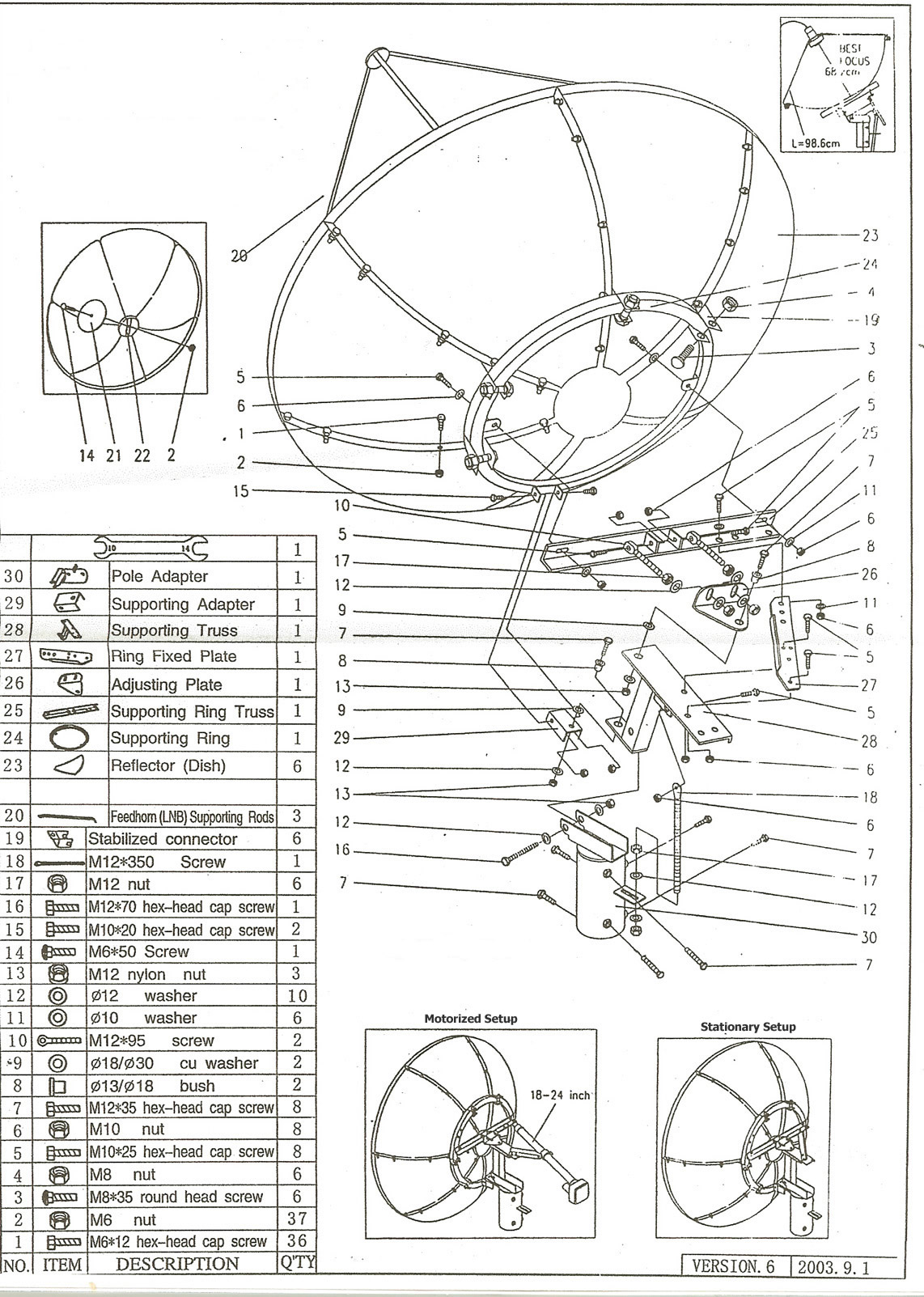
The bill of materials
>
Six reflective dish segments
>
Supporting ring
>
18" linear actuator for altitude (up/down)
>
24" linear actuator for azimuth (East/West)
> Ring fixed plate
>
Supporting ring truss assembly
>
Collector supporting rods)
Package 3
>
Solar tracking circuit
>
Pole Adapter
>
*Hardware
>
Dish center piece
*The bag of hardware contains the bolts for the dish segments, mounting ring brackets, and collector spars.
The rest of the hardware is already preloaded in the mounting frame or actuators.
Tools that will come in handy...
> Set of wrenches and/or sockets (I don't recall the exact sizes used)
> Flashlight (A small Mag-light works great for testing the sun sensor when there is no sun.)
> Small Flat-Head screwdriver (For motor wire terminals.)
> Small Phillips screwdriver (For access to controller circuit board.)
> Refreshments for your helpers
Step 1 - Mount (pole adapter) to (3" diameter ground pole). The mounting pole should be at least 3' tall.
Step 2 - Attach (12" linear actuator) between (pole adapter #30) and (supporting truss assembly #28 & #26)
Step 3 - Connect (dish segments #23) to each other. Be sure to include (supporting ring brackets) also called (stabilized connectors #19).
step 4 - Connect (supporting ring) to (assembled dish).
Step 5 - Connect (supporting ring truss assembly) to (supporting ring).
Step 6 - Connect (fixed ring bracket and 24" actuator assembly) to (supporting truss assembly)
Step 7 - Extend 24" linear actuator about 10 inches using your 12 - 36 VDC power supply.
Do not let the actuator shaft spin while you are extending it as it will change the preset limits.
(***CAUTION*** Linear actuators are very powerful... handle with extreme caution!!!)
Step 8 - Connect dish assembly to pole assembly at three points (Upper azimuth hinge bushing, Lower azimuth hinge bushing, and 24" linear actuator.
This is best done with at least two people!
Step 9 - Mount Dish center piece if desired.
Step 10 - Mount the (sun sensor bracket) to the outer bolt of any of the dish segment seams. See last three photos at bottom of this page.
I suggest mounting the sensor on the Eastern side of the dish. This will prevent the sensor from being shaded by the dish if the morning sun is missed due to overcast skies.
Step 11 - Mount the (sun sensor) to the (sun sensor bracket). See last three photos on this page.
Make sure the cable from the sun sensor leads in the tilt-down direction. This will align the mechanical axis with the electronic axis.
Step 12 - Connect the wires from the tracking controller to the appropriate actuators.
Don't replace the wiring covers on the actuators yet because you still need to check the polarity of the motor wires.
Step 13 - Connect your power supply wires to the power wires on the tracking controller. ***Double check your polarity***
If you are in the sun then the dish should start moving in about 10 seconds.
See if the dish is moving toward the sun in both axis. If not then determine which motor wires need their polarity reversed.
Disconnect the power to the controller first, then reverse the polarity of the motor wires.
Now
reconnect power to the tracking controller and observe... hopefully things are moving in the right direction now.
If you are not in the sun then you can shine a flashlight on the sun sensor cells to manually actuate the dish.
Remember that when it is dark there will be power supply voltage on the East/West motor wires even though the limit switch has disabled the actuator.
Step 14 - Run the dish to the East/West and Up/Down limits to make sure that the limit switches disable the actuators before mechanical jamming occurs.
The limits are preset but they need to be verified after every assembly. Do not let the dish run unattended until you check the limits.
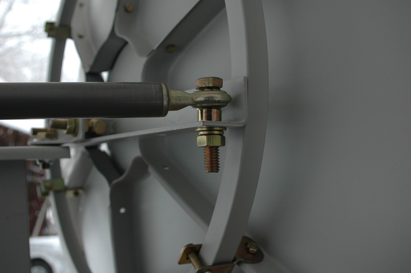
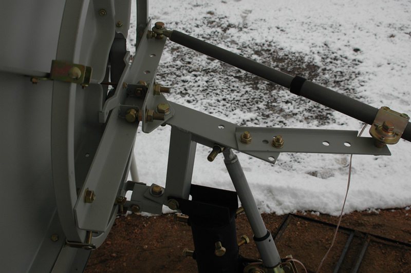
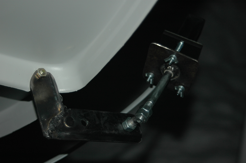
Azimuth actuator push rod hardware set.

Upper azimuth hinge hardware set.
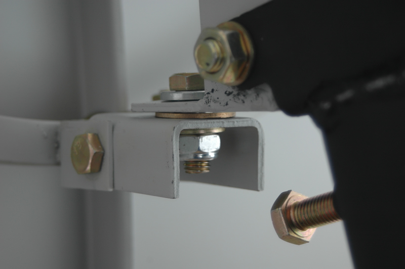
Lower azimuth hinge hardware set.
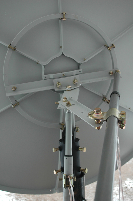
Dish rear view.
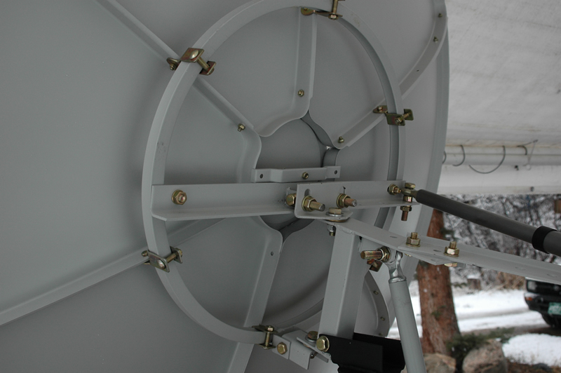
Another angle.
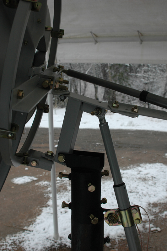
Elevation actuator setup.
Another angle.
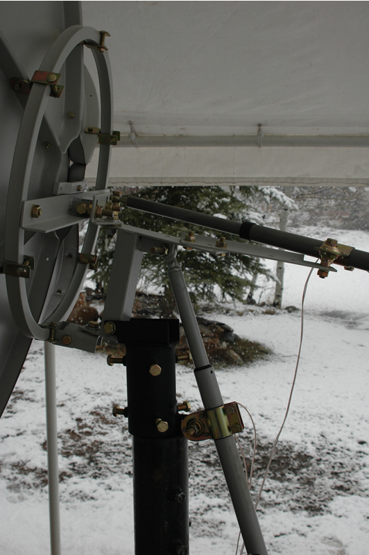
Yet another angle.
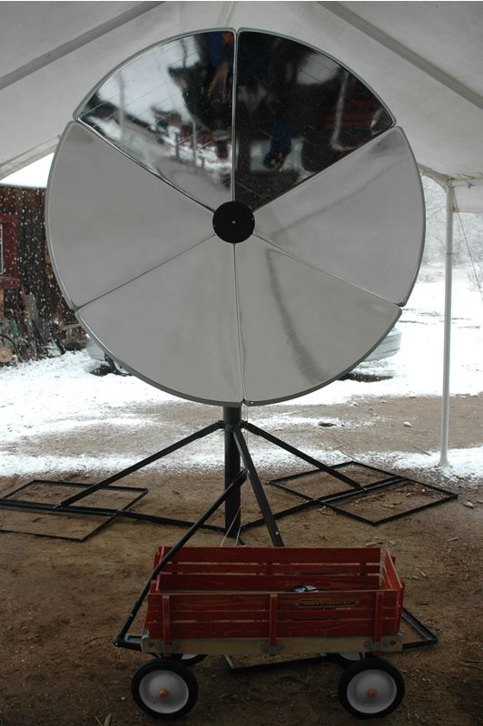
Front view. No sun sensor yet.
Sun sensor bracket.

Another angle.

Sun sensor mounting hardware.
|